

|
API 5CT T95 CASING TUBING SPECIFICATIONS |
||
| OD | 4-1/2“ to 20“/ 114.3mm to 508mm | |
| Wall Thickness | 5.21 mm - 16.13 mm | |
| Thread | STC, BTC, LTC | |
| Length | R1(4.88-7.62M), R2(7.62-10.36M), R3(10.36-14.63Meters) | |
| Standard | API 5CT | |
| Grade | J55, K55, M65, N80, N80-1, N80-Q, L80-13Cr, L80-1, L80-9Cr, C90, C95, T95, P110, Q125 | |
| Length Range | R1 (6.10-7.32m), R2 (8.53-9.75m), R3 (11.58-12.80m) | |
| Model in Common Use | 2-3/8", 2-7/8", 3-1/2", 4", 4-1/2" | |
| Specialties |
|
|
Physical properties are checked and each length hydrostatically tested, normally to only 3,000 psi in the plain end (unthreaded) condition. The following are also checked:
Part of this inspection is to drift all lengths.
Despite all the American Petroleum Institute (API) specifications and testing, some tubing defects are still found after delivery; thus, some operators do further inspection.
| Pipe Casing Sizes, Oilfield Casing Sizes & Casing Drift Sizes | |
| Outer Diameter (Casing Pipe Sizes) | 4 1/2"-20", (114.3-508mm) |
| Standard Casing Sizes | 4 1/2"-20", (114.3-508mm) |
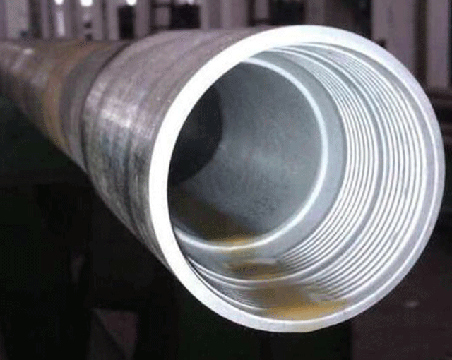
| Thread Type | Buttress thread casing, Long round thread casing, Short round thread casing |
| Function | It can protect the tubing pipe. |
|
Name of Pipes |
Specification |
Steel Grade |
Standard |
||
|
|
D |
(S) |
(L) |
|
|
|
(mm) |
(mm) |
(m) |
|||
|
Petroleum Casing Pipe |
127-508 |
5.21-16.66 |
6-12 |
J55. M55. K55. |
API Spec 5CT (8) |
|
Petroleum Tubing |
26.7-114.3 |
2.87-16.00 |
6-12 |
J55. M55. K55. |
API Spec 5CT (8) |
|
Coupling |
127-533.4 |
12.5-15 |
6-12 |
J55. M55. K55. |
API Spec 5CT (8) |
| C | Mn | Mo | Cr | Ni | Cu | Ti | P | S | Si | V | Al | |
| Min | - | - | 0.250 | 0.400 | - | - | - | - | - | - | - | - |
| Max | 0.350 | 1.200 | 0.850 | 1.500 | 0.990 | - | - | 0.020 | 0.010 | - | - | - |
| Tensile Strength | 724 MPa min | 105,000 psi min |
| Yield Strength | 655 MPa min | 758 MPa max |
| 95,000 psi min | 110,000 psi max | |
| Total Elongation Under Load | 0.500 % | - |
| Hardness | 25 Max HRC | 255 Max HBW |
| Group | Grade | Type | Total elongation under load % | Yield strength MPa | Tensile strength min. MPa | Hardness a max. | Specified wall thickness mm | Allowable hardness variation b HRC | ||
| min. | max . | HRC | HBW | |||||||
| 1 | 2 | 3 | 4 | 5 | 6 | 7 | 8 | 9 | 10 | 11 |
| 1 | H40 | - | 0.5 | 276 | 552 | 414 | - | - | - | - |
| J55 | - | 0.5 | 379 | 552 | 517 | - | - | - | - | |
| K55 | - | 0.5 | 379 | 552 | 655 | - | - | - | - | |
| N80 | 1 | 0.5 | 552 | 758 | 689 | - | - | - | - | |
| N80 | Q | 0.5 | 552 | 758 | 689 | - | - | - | - | |
| R95 | - | 0.5 | 655 | 758 | 724 | - | - | - | - | |
| 2 | M65 | - | 0.5 | 448 | 586 | 586 | 22 | 235 | - | - |
| L80 | 1 | 0.5 | 552 | 655 | 655 | 23 | 241 | - | - | |
| L80 | 9Cr | 0.5 | 552 | 655 | 655 | 23 | 241 | - | - | |
| L80 | 13Cr | 0.5 | 552 | 655 | 655 | 23 | 241 | - | - | |
| C90 | 1 | 0.5 | 621 | 724 | 689 | 25.4 | 255 | ≤ 12.70 12.71 to 19.04 19.05 to 25.39 ≥ 25.40 | 3.0 4.0 5.0 6.0 | |
| T95 | 1 | 0.5 | 655 | 758 | 724 | 25.4 | 255 | ≤ 12.70 12.71 to 19.04 19.05 to 25.39 ≥ 25.40 | 3.0 4.0 5.0 6.0 | |
| C110 | - | 0.7 | 758 | 828 | 793 | 30 | 286 | ≤ 12.70 12.71 to 19.04 19.05 to 25.39. ≥ 25.40 | 3.0 4.0 5.0 6.0 | |
| 3 | P110 | - | 0.6 | 758 | 965 | 862 | - | - | - | - |
| 4 | Q125 | 1 | 0.65 | 862 | 1034 | 931 | b | - | ≤ 12.70 12.71 to 19.04 ≥ 19.05 | 3.0 4.0 5.0 |
| a In case of dispute, laboratory Rockwell C hardness testing shall be used as the referee method. b No hardness limits are specified, but the maximum variation is restricted in accordance with 7.8 and 7.9 of API Spec. 5CT. |
||||||||||


